

I'd imagine that the venerable Dynaco ST-70 is the most well recognized tube amp in the world. It was introduced in 1959 and was sold until mid-1990. Over 300,000 of the ST-70s were produced, and more continue to be built as kits from companies like Tubes4HiFi and Triode Electronics. The Tubes4Hifi recreates the chassis exactly as it was (aside from heavier gauge stainless steel) with holes for screw-in posts, pre-amp power draw tube sockets up front, the stereo/mono switch, and other nostalgic things that aren't used today but will make your build look authentic. The Triode Electronics kit eliminates the superfluous holes in the chassis and makes use of a cap board inside rather than the tall quad cap, along with a different driver board.
Also popular are rebuild kits with newly engineered driver boards that one can use to improve an existing ST-70. There are new boards from Tubes4HiFi, Mapletree, DIYTube, WelborneLabs , Classic Valve Design (the high tech DynaMutt) and likely a dozen others out there, all with their own flavor and philosophy. After reading so much about the amp on various forums, I had the burning desire to put one together ;)
Also popular are rebuild kits with newly engineered driver boards that one can use to improve an existing ST-70. There are new boards from Tubes4HiFi, Mapletree, DIYTube, WelborneLabs , Classic Valve Design (the high tech DynaMutt) and likely a dozen others out there, all with their own flavor and philosophy. After reading so much about the amp on various forums, I had the burning desire to put one together ;)
I personally chose the kit available from Bob Latino from Tubes4Hifi as the cornerstone of my build. The kit is well documented and it seems that there has been a lot of thought in the parts selection. The kit includes the VTA70 driver PCB which was introduced in 1987, appeared in Glass Audio magazine in 1989 and continues to be offered today. Of course, building a kit stock is not my style, so the chassis and transformer bells were sanded and powder coated. I snuck in a few little upgrades too, including:
- Teflon Tube Sockets and PCBs
- Kimber TCSS wiring
- Cardas RCAs / Binding Posts / Input wire
- Kiwame / Takman Resistors
- Mundorf Coupling Caps
- Nichicon 100uF Electrolytics
- Pilot light
- Teflon solder strip for pentode / triode switch wiring
- Heavy Duty On/Off Switch
- Custom brass input and name labels
- IEC Plug
Holes had to be drilled/cut for the new RCAs, larger switch, pilot light, solder strip and IEC. Since the chassis is 16 gauge stainless, it takes a bit of effort. The binding posts required a little bit of modification but fit in the existing slots. I used black lacquer coated phenolic boards and drilled them out to hold the posts in place. The tube compliment is Sylvania JAN input tubes, Winged C output tubes and Sovtek rectifier.
Here's a few pics to enjoy:
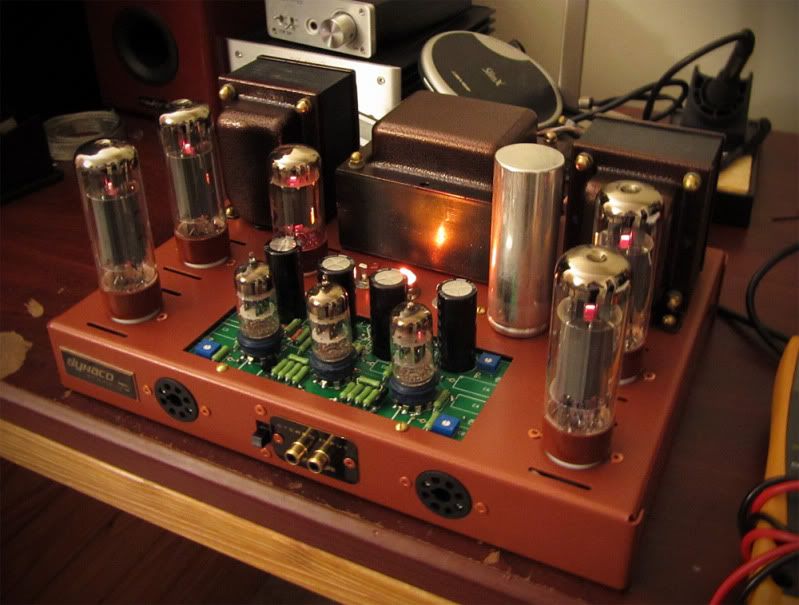 |
| ST-70 Running - Click to Enlarge |
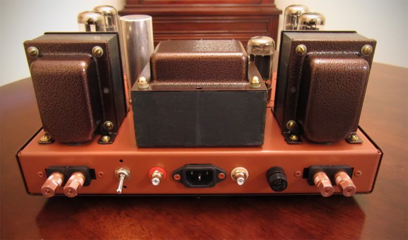 |
| ST-70 Back - Click to Enlarge |
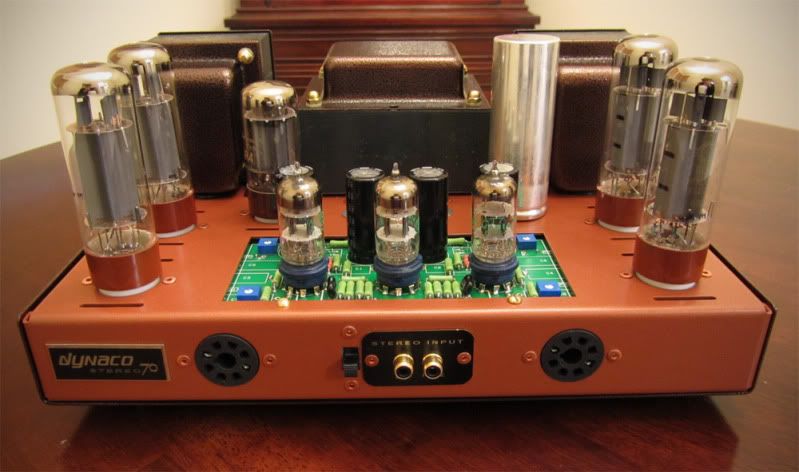 |
| ST-70 Front - Click to Enlarge |
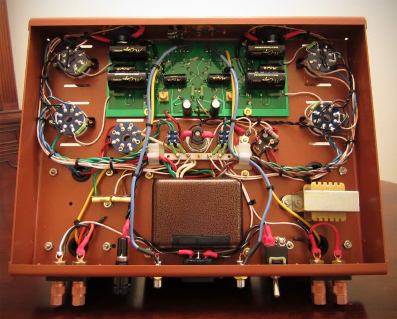 |
| ST-70 Guts - Click to Enlarge |
It was a fairly easy build and a recommendable kit. The sound is lush and engaging.
 |
Looking for Mundorf Capacitors for your build (among other great DIY parts)? Check out AuDIYo.com - Quality High End Audio Components and Parts. |
The Fine Print:
Please remember that building circuits and performing circuit modifications can be dangerous to you and/or your surroundings and should only be performed by a certified technician. The owner of this blog and all associated parties can not / will not be held responsible if you attempt a build or modification posted above and cause physical harm to yourself or your surroundings. Many electronics contain high voltages that can kill, and mods, if performed improperly, can be a fire hazard. Please keep this in mind.


Hi,
ReplyDeleteHow do you like the sound of your VTA 70? I built the kit stock with metal film resistors and find the sound a little bright for my liking. Basically I'm wondering if the Kiwami resistors would tame the sound.
Thanks
The Kiwame carbon films are more agreeable to my ears than the metal film, but resistor differences are more subtle than tube-rolling. Are you running Svetlana Winged Cs for power? They might be worth a shot before you break out the soldering iron.
ReplyDeleteI really like that custom panel for the RCA input jacks. Would you mind describing how you built it, and what with?
ReplyDeleteThanks! It actually didn't take much effort. The RCA openings were measured and I created a vector file with the fonts and openings. This was sent over to a brass engraver who dropped a black covered piece of brass into their machine and out it came. There are places online like US Brass Shop and Halex that can handle this for you.
ReplyDeleteWhen you say the kit was "well documented", do you mean like how my Bottlehead Crack is well documented? My reasoning is, you got crazy skills man, would a beginner be able to make this kit, or would you suggest I get more kits under my belt before attempting such a kit. Also, if the kit doesn't include any documentation on soldering and assembly, where should I begin? I've been harassing you on your blog lately, hope I'm not driving you bonkers yet! Lol
ReplyDeleteThank man.
No worries at all Matt, feel free to post as often as you'd like. Yes, the manual for the VTA-70 and VTA-70 driver board are very fleshed out, much like the Bottlehead kits. I don't recall if it documents soldering technique, so I'd recommend checking out the resources at the AMB Labs website: http://www.amb.org/audio/ and watching the soldering tutorial videos. I also recommend the book MAKE: Electronics by Charles Platt, it really goes over all the basics in a simple and easy to understand format.
ReplyDeleteThanks for the recommendations!! Actually, my wife has crazy soldering skills, I'm gonna get her to teach me (how many guys say that! Lol) I just downloaded the book MAKE: Electronics, sadly though, it seems to not discuss safety as it pertains to the type of voltages we deal with in amps. Although, in just scanning it quickly, I think it will be a huge help for basic electronic circuits. :)
ReplyDeleteIt's a great book, and will also teach you about solder joints and how to make a good one. There is some info on safety practices with high voltage at DIY Audio: http://www.diyaudio.com/forums/tubes-valves/30172-safety-practices-general-ultra-high-voltage.html
ReplyDeleteIf you have specific questions, it would be a great place to post them, as there are quite a few members at DIYAudio who have much more experience than me.
Thanks so much man!! :)
ReplyDeleteAre you getting any noise injection from having the RCA in the back so close the to AC lines and transformers?
ReplyDeleteI've had others ask me the same thing. Nope, no noise. The wiring for the RCAs is relatively thin at 24 gauge and is shielded, which I'm sure helps.
ReplyDeleteI have more than one dyna 70. I have one with the Dyna mutts mod. from Classic Valve Design from 2009. It use 6FQ7's as drivers, has the constant current source with the feedback loop around it. It sound a bit hard. Wondered if anyone out there experience this.
ReplyDeleteHave had more that one Dynaco 70. I have one with the Dyna mutts mod. It uses 6FQ7's for driver tubes, has the constant current source with the feedback loop around it. Although the amp performs well in many ways, I tend to he a bit of a hardness in the mids and hi's. I wonder if anyone share this opinion and if there is a simple way to get it sounding a bit sweeter.
ReplyDeleteTim
Beautiful! I may purchase one of Bob's kits soon. I must say the work you did on the chassis and transformer bells makes your amp fun to look at. Shiny chrome is always nice, but I'm afraid I'll not be able to build the kit without wishing it looked more like yours!
ReplyDeleteThanks for the kind words Shawn, highly appreciated. I'd love to see your build once you get underway. Bob offers a mean piece of kit for sure.
ReplyDeleteNice work. What type of bit did you use to drill the holes from the rca inputs? What size bit did you use? I'm assuming you used a drill.
ReplyDeleteHi Talmage, I used a stepped drill bit. You can get a cheap one from HarborFreight, or if you want to invest in a nice one, go to the electrical section of Home Depot and get one made by Klein.
ReplyDeleteLooks killer! Where did you place the pilot light in the circuit? Is it LED?
ReplyDeleteHi there Jake, if I recall correctly it's off the tube heaters. It is indeed an LED that works with the old bayonet style lights.
ReplyDelete