Zynsonix Link

Showing posts with label Switchbox. Show all posts

March 30, 2021

Headphone Switchbox in a Compact Chassis

A few years ago I made a headphone switchbox. It was popular enough that I added it for sale on Zynsonix. It uses a standard Hammond chassis which is made in Canada. There have been people looking for a more compact version. Unfortunately Hammond doesn't make a super compact extruded chassis from this line, however a fellow over at HeadFi, ScornDefeat, was able to find a smaller chassis that fits everything (just barely). I believe it's the same chassis as the Objective 2 headphone amp. The size is 3.15" x 5.25" x 1.37" / 80 x 134 x 35mm (LWH) and it comes in anodized black, silver, or blue. 

Rather than Electroswitch in the previous build, the similar 3 pole Lorin CK-1460 is used, and rather than the flashier Neutrik NMJ6HC-S with silver hexagon design, the plain black NMJ3HF-S is used. These are all about the same size so should be interchangeable. 

The knob is a 1/4" Kilo machined aluminum knob. I prefer the selector on the right as it's a little more natural to use the right hand to switch outputs. 

One oddity to note is the chassis that came from Amazon had tapered head silver screws and the chassis screw holes needed to be threaded (Hammond chassis comes pre-threaded). 


If you'd like to build one of these yourself, it shouldn't take longer than 2-3 hours. I recommend solid core 24 AWG wiring for headphone signal wiring inside of a chassis. 

If you'd like one of these built for you for your headphone switching needs, reach out to Zynsonix


June 12, 2020

Balanced XLR Switchbox - Audio Design HAS-3LB

When it comes to passive balanced switchboxes, there aren't a whole lot of off-the-shelf options out there. It's not uncommon to just build them from scratch with a nice switch and point-to-point wiring as they're not terribly complicated.

I recently learned of a Japanese audio company called Audio Design that offers a simple but solid 3 in, 1 out balanced switchbox. The outside is a straight-forward design with a dark blue and silver aluminum box with a brushed aluminum front panel. The only control is the single selector knob up front to switch between the 3 outputs. What counts though is the inside, where there is a high-quality Seiden selector switch, some high-quality Neutric XLR jacks, and some thick copper wire... which appears to be 18 or 20 gauge. 


Balanced XLR Switchbox - Audio Design HAS-3LB

Balanced XLR Switchbox - Audio Design HAS-3LB


One of my clients owns the unit, and wanted to take it to the next level. The Seiden switch is already top-notch, could stay, but we'd replace the copper wire with solder core silver wire in Teflon tubing, the XLRs with the shiny and beautiful Cardas XLRs, and the generic plastic feet with EAR isodamp feet. 

I will say in advance, if you will be using the Cardas CM F and CM M XLRs, you better have a solder pot. The rhodium plating is not terribly interested in taking on solder so the areas where the wires connect need to be submerged in very hot solder for 10-15 seconds before they will be responsive. I personally use an American Beauty MP-9 solder pot for small jobs like this. I turn it on to the highest temp and let it warm for an hour before using. Kester low dross solder works well. 

Once all the Cardas XLRs had been prepped, the old Neutrik XLRs were removed from the rear panel and replaced. They are the same DIN dimensions, so no need to change the hole sizes or shapes. Note that the Cardas units have pins can comply to some extent thanks to a soft material surrounding them. I don't know if this was done for vibration damping or maybe the tolerances aren't super tight, but just an observation. 

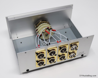
The 24 gauge solid silver is then hand-sleeved in Teflon tubing and attached to each terminal. One should note to not make the paths too short or tight, as this will pull on the decks of the Seiden switch and cause there to be less surface area for the gold plated contacts to press upon. I chose to add heatshrink tubing over the solder contacts as silver will oxidize over time. The oxidation is still conductive, but it doesn't look as nice. Also it keeps the joints secure when shipping. 

 
Balanced XLR Switchbox - Audio Design HAS-3LB

Balanced XLR Switchbox - Audio Design HAS-3LB

Balanced XLR Switchbox - Audio Design HAS-3LB

Balanced XLR Switchbox - Audio Design HAS-3LB


The feet on the unit are attached with screws into threaded holes. There are no nuts or lock washers to worry about, so switching them is quick and painless. 

Whether modded or not, I think the Audio Design HAS-3LB is a very solid unit with no real shortcomings other than a slightly vanilla design. Should you wish to extract every bit of performance out of a stock unit, reach out to zynsonix.com for pricing information. 


Disclosure: Please remember that building/modifying circuits can be dangerous to you and/or your surroundings and should only be performed by a certified technician. The owner of this blog and all associated parties can not / will not be held responsible if you attempt a build or modification posted above and cause physical harm to yourself or your surroundings. 

November 10, 2016

Balanced Audio Switchbox - Audiophile Quality

If you're an audio purist, it can be worrisome adding components in the signal path, even if it enhances convenience during your listening sessions. This is compounded even further if you are taking a delicate signal from a turntable to a phono pre. It doesn't make sense to to spend all that money on fancy interconnects if they are plugged into a switchbox with a low-quality switch, forcing the signal to travel across questionable metal contacts that may not be making a secure connection. That being said, everyone appreciates being able to change inputs and/or outputs at the turn of a knob. There's an easy solution, use the best materials available so the switchbox will be as transparent as possible.

A great client of mine, Todd, wanted a balanced switchbox that would fit conveniently on his rack and not harm the signal. Based on the sizing constraints, he chose a size that would match his Schiit Audio Mjolnir 2 headphone amplifier and fit conveniently underneath. We selected a Par-Metal 16" wide aluminum case (20-16123x) that matched the dimensions perfectly, anodized with alodine for EMI/RFI shielding, and black on the exterior.

Par Metal aluminum chassis 20-16123x

The unit would have a single pair of balanced XLR inputs, and four pair of balanced XLR outputs. I selected the Neutrik DLX series with heavy duty shielding. As Neutrik states on their page: "[the] all metal housing works in combination with a new duplex ground contact yielding the best RF protection and ground conductivity in a chassis mount XLR". Creating the holes in the back chassis panel simply requires using a ruler to plan out where the holes would be cut. Greenlee makes an excellent punch for D-size mounting dimensions. The D mount specification calls for a 23.80mm (0.9370") diameter hole, but a 15/16" hole is 0.9375" and works perfectly well. As you've likely seen in many of my other posts, I use these punches a lot. You drill a pilot hole, insert the bolt and tighten with a ratchet and you get a nice accurate punch every time.


Greenlee 15/16" Metal Punch

The XLR connectors can be inserted from the back for a clean mount. I chose to use pop-rivets to install the connectors as I like the look, however, a screw, nut and lock washer would also suffice. 

Aluminum pop-rivet

Installing the D mount XLRs on the back panel 

Below you'll note the D-mount XLRs installed. Despite being directly installed to the metal chassis, solid grounding is very important, so a bus wire is run across the chassis ground pin on each unit, and each unit is shorted to the metal surrounding the plug. You'll also note the mount for the switch has been installed a little past the halfway point on the chassis.


Bottoms up!


And here comes the fun part, wiring. I encourage labeling the chassis interior which won't be visible after completion so you don't get mixed up during the wiring process. In this case, one wafer (or level) on the switch is dedicated to the right signal (both positive and negative), and the other to the left (+ and -). At any given time, four connections are being made: L+, L-, R+, R-. The Elma switch selected is really nice quality, make before break, with Swiss movement, gold plated connectors, the works. Solid core UP-OCC in teflon wire is being used for all connections. The shaft extension rod is a general cut-to-size unit with lock-nuts and a brass fitting. 


Wiring up the Elma switch

I do like to tidy up the wiring after the fact with a few zip-ties, although this is not a necessary step. 


For a nice finishing touch, brass plates are engraved to fasten to the chassis.


The front art I created in Adobe Illustrator in EPS format so the engravers could use it. This was the design Todd and I collaborated on. The knob is knurled aluminum from Goldpoint and has a nice solid weight and feel. I added a bit of J.B. Weld to the connections on the shaft extension to ensure they wouldn't loosen up over time and annoy poor Todd.

Engraved brass plate

Goldpoint milled aluminum knob


And some final photos to see the finished product. The footers are EAR isolation feet.


Balanced Switchbox Front


Balanced Switchbox Back

The Fine Print:
The above steps detailing the creation of a switchbox are for entertainment purposes only are not intended to be instructional. The owner of this blog and all associated parties can not / will not be held responsible if you attempt the process posted and cause physical harm to yourself, your surroundings or your property.

June 8, 2012

Custom RCA Switch Box for Audio

So in any given audio setup there may be multiple amplifiers (e.g. a headphone amp, speaker amp, etc.) or possibly multiple sources (e.g. a record player, CD player, DAC from a computer, etc.). A switch box keeps it simple so one doesn't have to reach in the back of the rack and manually switch interconnects to listen to particular equipment. They will commonly have multiple RCA jacks (or in some cases XLR jacks) for both input and output and a switch which is commonly 2 pole (stereo with common ground) or 4 pole (stereo with isolated grounds).

They may be handy, but not all switch boxes are created equally; audio enthusiast know that using a generic one can potentially degrade the audio quality, a situation which just isn't worth the added convenience. All the ingredients need to be of high quality to ensure there is no notable degradation of the signal.

This post will be detailing a simple 6-to-1 switch box making use of high quality parts to ensure transparency. Parts include a Swiss-made Elma 04-1264 switch, EAR isolation feet, Philmore Teflon insulated gold plated RCAs, Neotech UP-OCC sold-core copper wire in Teflon and a lovely custom-made chassis from Keith (ebay seller po1019).

The first task was to take the chassis and drill holes for the switch, feet, and RCA connectors. It may be easy to use a ruler and mark where each hole is going to be, but drilling the holes perfectly in line *probably* won't happen, even on a drill press. When there are multiple items lined up, the eye can very easily identify any slight aberrations to a straight line. I was able to get them pretty close in this case. The chassis was then powder-coated a nice cream color.

Chassis prepped for the build process

The next process is installing the RCAs. Because the powdercoat insulates the aluminum, the back of the holes were filed so the RCAs would ground to the chassis so the chassis would act as a shield. You might be gawking at the Philmore RCA blister pack and thinking "wow, that looks like dollar store garbage"... Looks can be deceiving; under the homely packaging are a pair of very nice quality gold RCAs with Teflon insulation. I like to use Cardas RCAs in many of my builds, but when one is using seven pair, like in this case, that would be quite costly; that's where the Philmores come into play. Each one is cranked on using a socket wrench and the ground washer bent at 90 degrees. 

The chassis populated with Philmore RCAs

Each of the ground washers is then tweaked together with a pair of pliers and a ground wire is run through them, then soldered in place. This particular wire is silver but any bus wire would be fine. This ensures that there is a common ground between all inputs and outputs. 

Ground wire connected to each RCA

Now comes the fun part; wiring up each RCA to the Elma switch. Seeing which solder lug corresponds to each switch position is relatively straight forward, simply look through the transparent plastic at the location of the gold contacts. Each wire is soldered in place and a small amount of heatshrink is placed over the connection. 

Beginning the wiring process

The Neotech wire was kept nice and short for each connection. On the bottom, EAR isolation feet were fitted with a screw, lock washer and nut.

Wiring complete

The box could now be assembled and the nicely finished wood panels placed on the sides. Below are a few photos of the finished product.

Switchbox complete!

Switchbox Front

Switchbox Rear

Switchbox Bottom

Some nice points about this design are the short signal paths thanks to the small chassis, the Teflon insulated wire and RCAs, the gold contacts on the switch and the point to point wiring with no circuit board for the signal to run through. This box could either be used to allow 6 inputs and 1 output, or 1 input and 6 outputs. With a larger box and a second switch, there could be both multiple inputs *and* outputs. Or there could be two of these boxes daisy-chained, allowing for 6 inputs and 6 outputs. Tons of options!

Update: I created a nice little logo "iO" standing for input output and had it custom engraved on a brass plate for the top panel. Looks rather sharp I think :) Some additional photographs with the plate are below.


Need a great sounding passive audio switchbox to tie your system together? Please contact Zynsonix Audio for details. 


The Fine Print:
The above steps detailing the building of a switch box are for entertainment purposes only and not to be performed under any circumstances. The owner of this blog and all associated parties can not / will not be held responsible if you attempt the process posted and cause physical harm to yourself, your surroundings or your property. Please keep this in mind.